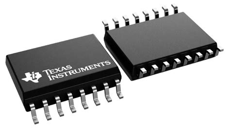
Empowering I2C Communication with the PCF8574ARGYR: A Comprehensive Guide
Introduction
The PCF8574ARGYR is an indispensable integrated circuit (IC) for interfacing microcontrollers with parallel devices over the I2C bus. Its versatile capabilities have revolutionized the design of embedded systems, simplifying communication and enhancing functionality. This comprehensive guide delves into the world of the PCF8574ARGYR, exploring its features, applications, programming techniques, and best practices.
Understanding the PCF8574ARGYR
The PCF8574ARGYR is a 8-bit I/O expander, designed to extend the input/output (I/O) capabilities of microcontrollers. It operates over the I2C bus, a widely used serial communication protocol, allowing seamless communication between microcontrollers and various devices.
The PCF8574ARGYR features:


- Eight programmable I/O pins
- Addressable via its unique I2C address
- Configurable as input or output pins
- Interrupt output for event-driven programming
Applications of the PCF8574ARGYR
The PCF8574ARGYR finds applications in a wide range of embedded systems, including:
-
Expanding I/O capabilities: Extend the limited I/O ports of microcontrollers to control additional sensors, actuators, and peripherals.
-
Interfacing legacy devices: Connect to older peripherals that use parallel communication interfaces.
-
Reducing microcontroller workload: Offload I/O tasks from the microcontroller, freeing up its resources for more critical tasks.
-
Creating versatile multi-master I2C networks: Enable multiple microcontrollers to communicate with each other and share I/O devices.
Programming the PCF8574ARGYR
Programming the PCF8574ARGYR involves configuring its I2C address and controlling its I/O pins. This can be achieved using a microcontroller or an I2C master device.

-
Configure I2C Address: The PCF8574ARGYR is addressable via a unique 8-bit I2C address, typically set to 0x20 by default. This address can be modified using the A0, A1, and A2 pins.


-
Set Port Direction: The PCF8574ARGYR's I/O pins can be individually configured as inputs or outputs. This is achieved by writing a byte to the configuration register (address 0x03), where each bit corresponds to a pin. A logic '0' sets the pin as input, while a logic '1' sets it as output.
-
Read/Write I/O Data: To read the state of the I/O pins, a microcontroller sends a read command to the PCF8574ARGYR's input register (address 0x00). To write data to the pins, a write command is sent to the output register (address 0x01).
Benefits of Using the PCF8574ARGYR
The PCF8574ARGYR offers numerous benefits for embedded system design:
-
Simplicity: Its I2C interface simplifies communication, eliminating the need for complex parallel interfaces.
-
Versatility: The configurable I/O pins allow for a wide range of applications and device interfacing options.
-
Efficiency: Offloading I/O tasks from the microcontroller improves performance and reduces power consumption.
-
Cost-effectiveness: The PCF8574ARGYR is a low-cost solution for expanding I/O capabilities.
Common Mistakes to Avoid
While using the PCF8574ARGYR, be cautious of the following common mistakes:
-
Incorrect I2C Address: Ensure that the I2C address of the PCF8574ARGYR matches the one used in the microcontroller's software.
-
Overloading Output Pins: Avoid exceeding the maximum current limit of the PCF8574ARGYR's output pins.
-
Underpowering the I2C Bus: Ensure that the I2C bus voltage is within the specified range for stable communication.
-
Ignoring Input Thresholds: Consider the input threshold levels of the PCF8574ARGYR's input pins to avoid incorrect readings.
Step-by-Step Approach to Using the PCF8574ARGYR
Follow these steps to successfully use the PCF8574ARGYR:
-
Hardware Setup: Connect the PCF8574ARGYR to the I2C bus and power it up.
-
I2C Initialization: Initialize the I2C communication protocol in the microcontroller.
-
Configure Device Address: Set the PCF8574ARGYR's I2C address if necessary.
-
Configure Port Direction: Determine the required input/output configuration for the I/O pins.
-
Read/Write I/O Data: Use I2C commands to read from or write to the PCF8574ARGYR's input and output registers.
FAQs
-
Q: What is the maximum I/O voltage range of the PCF8574ARGYR?
A: Up to 6V

-
Q: Can the PCF8574ARGYR be used in interrupt-driven applications?
A: Yes, it has an interrupt output pin for event-driven programming.
-
Q: What is the maximum data transfer rate supported by the PCF8574ARGYR?
A: Up to 100kbps
-
Q: Is the PCF8574ARGYR suitable for use in low-power applications?
A: Yes, it features low power consumption modes.
-
Q: Can multiple PCF8574ARGYRs be connected to the same I2C bus?
A: Yes, as long as each device has a unique I2C address.
-
Q: Is the PCF8574ARGYR compatible with both 3.3V and 5V systems?
A: Yes, it operates at a voltage range of 2.5V to 5.5V.
Conclusion
The PCF8574ARGYR is a versatile and powerful I/O expander that empowers embedded system designers to extend the capabilities of their microcontrollers. Its simplicity, efficiency, and cost-effectiveness make it an indispensable tool for a wide range of applications. By understanding its features, programming techniques, and best practices, developers can harness the full potential of the PCF8574ARGYR and create robust and reliable embedded systems.
